Introduction
Hello! This will be a first, experimental post in a little series of blog posts detailing a complete workflow – hopefully useful to someone who might be wanting to use the laser cutter or work on a small project.
Recently, I’ve been playing with our space’s laser cutter with a couple of simple projects. My most recent was a branded flyer holder for Innovate Guildford, a recent event we attended – which came out great!
My first eyeballed design of the stand – done in Fusion 360, my CAD software of choice – would tip backwards with a light touch. It was also quite a tight fit, which required a visit from a persuader to assemble everything correctly. I quickly edited the design in F360 and made the side panels extend behind more to give a bit more support, and changed the kerf adjustment size from 0.3mm to 0.15mm (kerf is the size of the laser beam, and adjusts your design accordingly – a simple rule of thumb is a smaller kerf adjustment = looser fit).
This was the thing that really cemented the usefulness of the laser for me – a quick design change, set up the laser, make the cut, and replace the side panels took all of 5 minutes to do. Try that design change on a 3D printer, and you’ll be waiting a while.
The result was nice too – it fit together much more smoothly thanks to the kerf adjustment, the simple engraving on the front adds a touch of custom flair, and of course, it performed its job of holding our flyers very well.
Going from start to finish like this isn’t quite as hard as it seems. Neither is Fusion 360. In this little series of blog posts I’d like to approach something a little more complicated, which is to make a laser cut case for a small electronic widget – the Bus Pirate.
What’s a Bus Pirate?
No, not that. A Bus Pirate is a very handy little gizmo for electronics work – designed by Ian Lesnet and produced through Dangerous Prototypes. A simple look at the BP shows that its main purpose is for talking to electronics over a variety of protocols, such as I2C, SPI, 1-Wire, JTAG, MIDI etc. It can also act as a power supply, logic analyser, oscilloscope, ICSP programmer, and really, anything you might want to do with interfacing your computer to a component or circuit.
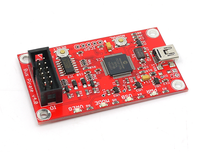
I own one of these guys – specifically, the V4.0 version, and admittedly I have used it a handful of times – I’m simply not that good enough at electronics (yet!) to have needed it. However, when I do, I can reach for it with confidence that it will help me out.
Currently, the BP sits in a component box alongside it’s probe lead, a cheap Chinese logic analyzer clone, and some other bits and bobs. While I’m sure the PCB, with it’s mostly low profile SMD components, will be relatively safe from harm if I transported it separately, there is something reassuring and polished about having it in its own case – hence the start of this project.
Case features
As always, it’s good to start out with a few objectives, or specifications, before we even start designing. Let’s define what I want this case to provide and why:
- Made from laser cut acrylic. Acrylic is nice, easy to cut, pretty cheap, and colourful. There’s a plethora of material options available, and I’ve used it already.
- Cutouts for the business parts. There’s a mini-USB connector, the 12 pin shrouded connector for the probes, and an ICSP pin header. Access to these is the main function of the board, so it would be pretty daft to make them unusable. We need to bear in mind the sizes of the relevant connectors that will be plugged in to them.
- Visibility of the 4 status LEDs on the top. The LEDs are coloured, and while easy to distinguish their function from their location, it might be nice to make them easily visible with uncoloured, clear acrylic.
- Button pushes. There’s two buttons on the board, ‘Normal’ and ‘Reset’. Limiting access to these will always lead to frustration some day, so we could either add small holes for access for a pokey thing (technical term), or include some parts in our design to extend the buttons to the surface.
- Labelling – engraved labels for the LEDs, buttons, and even pinouts would be very useful. The main connector takes a colour coded probe lead. If we can somehow add the colour codes for quick and easy identification, this would be very handy.
- Sturdy – I’m not saying this will be subjected to abuse, but it’s reassuring to know that it can take a few hits.
We’ll likely add more and take some out, and even iterate over the design, but before diving in it’s always worth taking our time to spec our design out and have some goals in mind.
Metrological!
Because we’re designing a case for an existing thing, it makes sense to get an accurate reference design of it as our first task. Sure, the flyer stand had this – we needed to know how big an A5 flyer was, to make sure it did its one main function properly – holding them! This wasn’t a hard task to accomplish, but our Bus Pirate is slightly more complex. We have the board size, mounting holes, LED positions and of course those connectors to deal with.
We have a few options of how to approach this. We could reach for our vernier calipers and measure everything up – or we can cheat, which is what I like the sound of. Being open source hardware, Dangerous Prototypes allow us access to all the design files. In this case, the board designs are in Eagle format – not my preferred choice (KiCad 4 lyf <3), but free and easy to install.
Now this next part took a lot longer than expected. There are a few options out there for taking an Eagle .brd file and getting some designs out of it – exporting to DXF, for example. There are promises of “easy” Eagle to Fusion 360 workflows, where the board and its components are sent over as a 3D model. Sadly this didn’t work – neither did exporting to KiCad, and some other things.
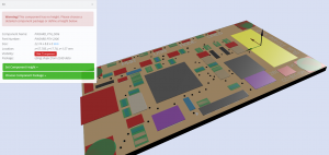
What did work for me was a nifty website, ecad.io, which will happily take an Eagle .brd file and spit out a .STEP file. This wasn’t without problem, as all the components had no height thanks to (I think) it being an old version of Eagle. Thankfully the web interface made it easy to set the heights of the important components, and as it was late and I was feeling lazy this would do for my purposes. Looks like I will be using those calipers after all.
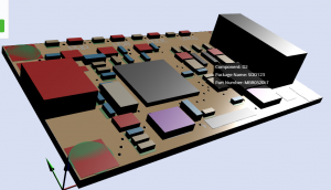
A few clicks later and editing the depths wasn’t nearly as hard as I thought it’d be. I measured the important components (connectors, switches, and LEDs) and guesstimated the rest. Thankfully the interface recognises all component shapes/packages of the same kind would have the same height, so you only have to enter the custom height in once for each package type.
For me, this is good enough for our design – all the important stuff is preserved and is more or less accurate.
A few more clicks, a bit of a wait for processing time, and I have a .STEP file of the Bus Pirate based off the actual board design.
Fusion 360 Beginnings
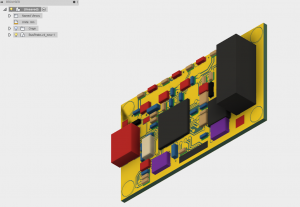
First off, let’s create a new project – a container that represents all of the files related to our case design. Even after using F360 for a few months, I’ve ended with reams of files and have found the cloud-based project approach refreshing.
After creating a project, I can click File > New Design From File and import our new .STEP file to create a component. Nothing exciting to say here – it took a few seconds to import while F360 thought about things, and it appeared. A slight mishap is that the mounting holes are filled in, I think because they were considered components in ecad. Not a problem though as the mounting hole is still there and selectable, and that’s all we need.
A quick test with the Inspect tool (shortcut ‘i’) confirms that the board is the same size as the one in my hand.
That’s it for part 1! In part 2, we’ll start designing the case from the imported board model, keeping in mind our design specs. Stay tuned for more 🙂